A look at what I've designed, how I approached it, and what I learned along the way.
Freshman · PLTW IED
Sight Board
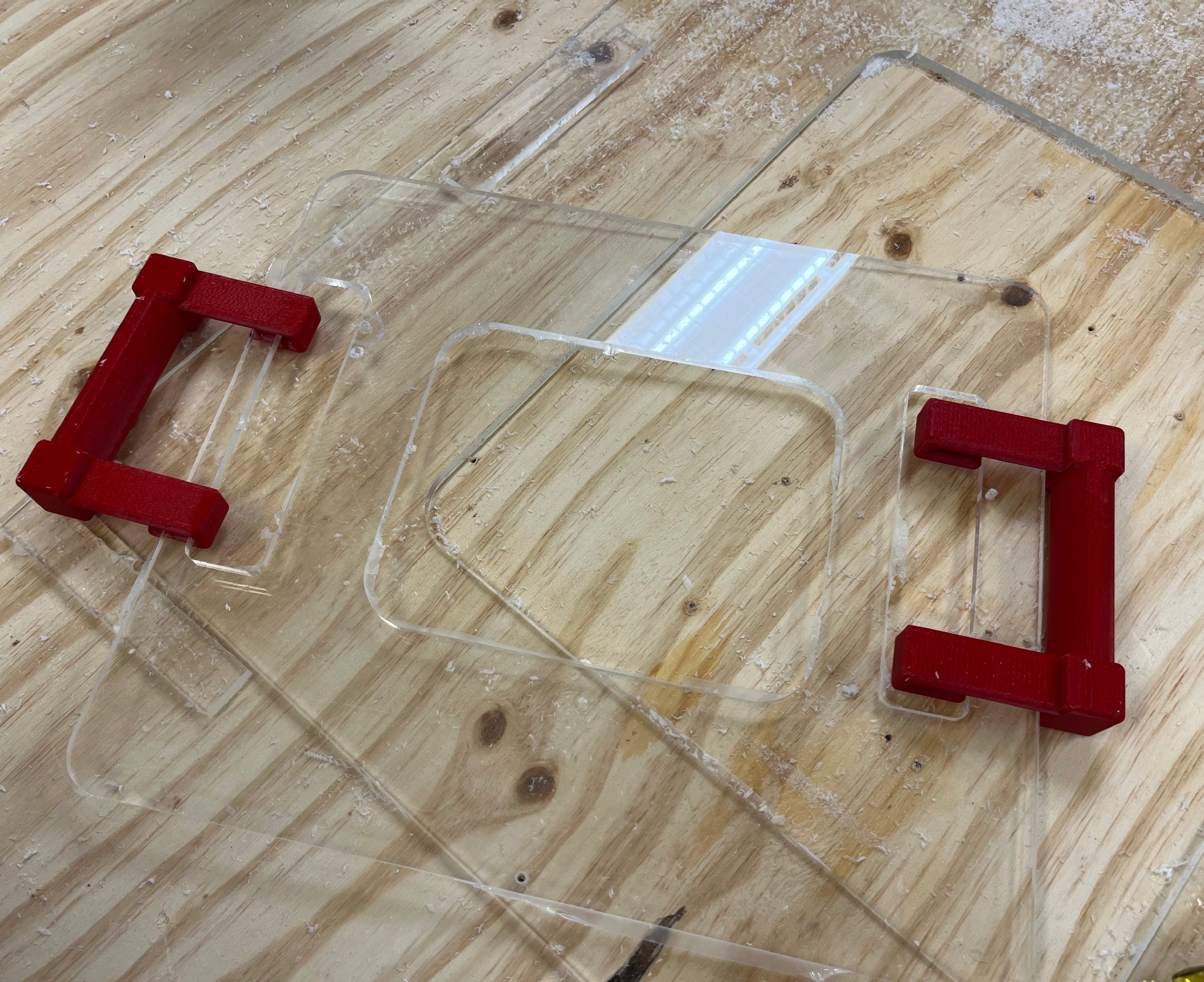
An assistive device designed for a disabled student who needed a way to communicate with their caregiver. I handled the CAD, material selection, and manufacturing from start to finish, including CNC-cut acrylic and custom 3D-printed handles.
A hand-cranked carousel automaton that uses snail and circular cams to produce synchronized rotational and vertical motion. This was my first experience designing a mechanical system with moving parts.
Cam MechanismsFusion 360Laser CutPrototyping
See My Process →
Coming Soon
In Progress
FRC Team 2022 Rebuilt by Haas Robot
Built by Team 2022 to compete in the 2026 Rebuilt by Haas FIRST Robotics Competition
Freshman · PLTW IED · CAD & Manufacturing
Sight Board for Disabled Student
Problem
A disabled student needed a tool that would help them interact with visual cues in the classroom. The device had to be easy to use, durable enough for daily use, and simple enough to pick up without much explanation. It also needed to be lightweight and safe, with no sharp edges.
Role
I was responsible for the CAD modeling, material selection, and manufacturing. This was my first time taking a project from a sketch all the way through to a finished physical object, and it pushed me to think carefully about how design decisions I make in CAD translate to real life.
Design Process
Client Meeting
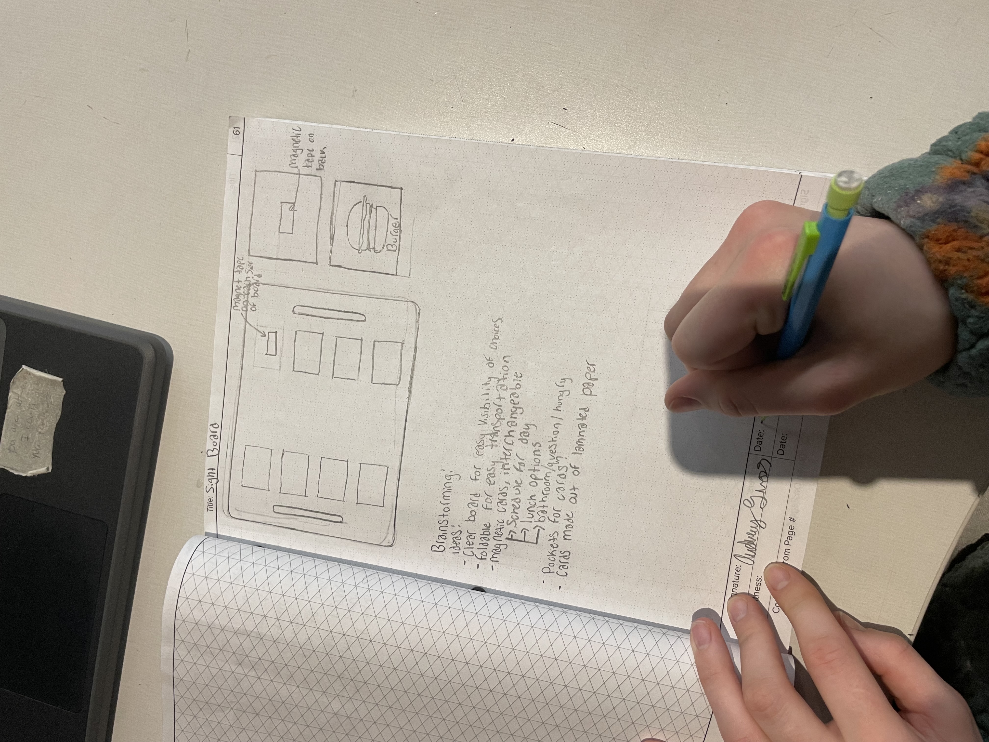
Hand-drawn sketch guiding the first discussion with the client.
I started by sitting down with the client to understand what they actually needed. I brought an initial sketch to give us something concrete to react to, which made the conversation a lot more useful. The client was flexible, which gave me some design freedom, but it also meant I had to think ahead about what would actually be practical to build.
Defining Criteria & Constraints
Design requirements: Clear, sturdy, compact, easy to hold, and no sharp edges.
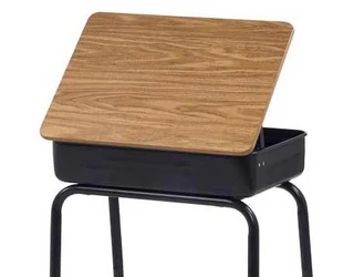
The classroom desk informed sizing and ergonomics.
Constraints: $40 budget and three 1.5-hour class periods to get it done.
Key challenge: Finding the right acrylic thickness was harder than I expected. It needed to be strong enough to hold up in a classroom setting but light enough to be portable, and it had to work with the CNC machine we had available.
CAD Modeling
I modeled all the components in Fusion 360. The snap-on handles went through several iterations before I got the fit right, which taught me a lot about tolerances and why small measurement decisions matter more than you would think depending on material choice.
Material Selection
Component
Material
Reason
Main board
Acrylic (¼ in.)
Clarity, rigidity, CNC-compatible
Handles
PLA (3D printed)
Lightweight, customizable geometry
CNC Fabrication & Final Assembly
The acrylic panel was cut on the CNC router using G-code I generated from Fusion 360's CAM workspace. Getting the feed rate and spindle settings right took some trial and error since acrylic cracks easily if you push it too fast. I ended up having to update the settings because the chips were melting together as the CNC cut the material. The PLA handles needed a few rounds of adjustment before they fit the way I wanted.
Reflection
This was the first project where I was responsible for the whole thing, not just one piece of it. Going from a sketch on paper to something a real person would use in their day made the design process feel a lot more concrete.
It also made me think more carefully about who I was designing for. The device was not for me, so my instincts about what was intuitive or comfortable did not always apply. That was a useful thing to figure out early.
Freshman · PLTW IED · Mechanical Design
Mechanical Automaton
Problem
The goal was to design and build a hand-cranked automaton that told a simple story through motion. It had to demonstrate real mechanical principles like cams, rotational motion, and linkages, and the mechanisms needed to be visible so you could actually see how the motion was being produced.
Role
I led the mechanical design and CAD modeling. That meant coming up with the concept, figuring out which types of cams to use, modeling everything in Fusion 360, and working through the physical prototypes when things did not move the way I expected.
Design Process
Initial Sketches
I started with hand sketches to figure out how to turn rotation from a hand crank into multiple different motions at once. The story I wanted to tell was about a mother and daughter at a carnival. The carousel is broken, so the horses spin but do not move up and down the way they should. The mother notices her daughter is disappointed, so she lifts her up and down herself to give her the experience the ride was supposed to. Getting that concept on paper helped me work through which cam profiles I needed and how everything could share one axle without interfering with each other.
CAD Design
Once I had a layout I felt good about, I moved into Fusion 360. This was my first time modeling a system where the parts actually interact with each other rather than just sitting still. I designed two cams on a shared axle: a snail cam to drive the vertical motion for the figures, and a circular cam to transfer rotation to the carousel. A lot of the work here was making sure there was enough clearance between parts and that the motion paths would actually work once everything was built.
Prototyping & Testing
Cardboard prototype used to evaluate motion, stability, and scale.
Before committing to final materials, I built a cardboard version to test the scale and motion. It immediately showed me that the vertical axle for the carousel was too tall, which made the whole structure tilt when it rotated. I shortened the axle and made the enclosure wider to fix it. That cardboard prototype saved me from making the same mistake in wood and PLA.
Final Assembly
Completed automaton demonstrating synchronized rotational and vertical motion.
The final version used 3D-printed cams, bushings, and a hand crank, wooden dowels for the axles, and a laser-cut wooden enclosure. During testing, the cams were not generating enough friction to spin the carousel consistently. I fixed it by wrapping a rubber band around the horizontal cam, which gave it enough grip to transfer the motion reliably. It was not the most elegant solution, but it worked.
Reflection
The friction problem with the cams was frustrating at the time, but looking back it was one of the more useful things that happened. It taught me that problems showing up late in a build are not failures in the design process, they are just part of it. The rubber band fix was unglamorous, but figuring out why it worked helped me understand the mechanics better than if everything had gone smoothly from the start.